1
2
3
4
5
6
7

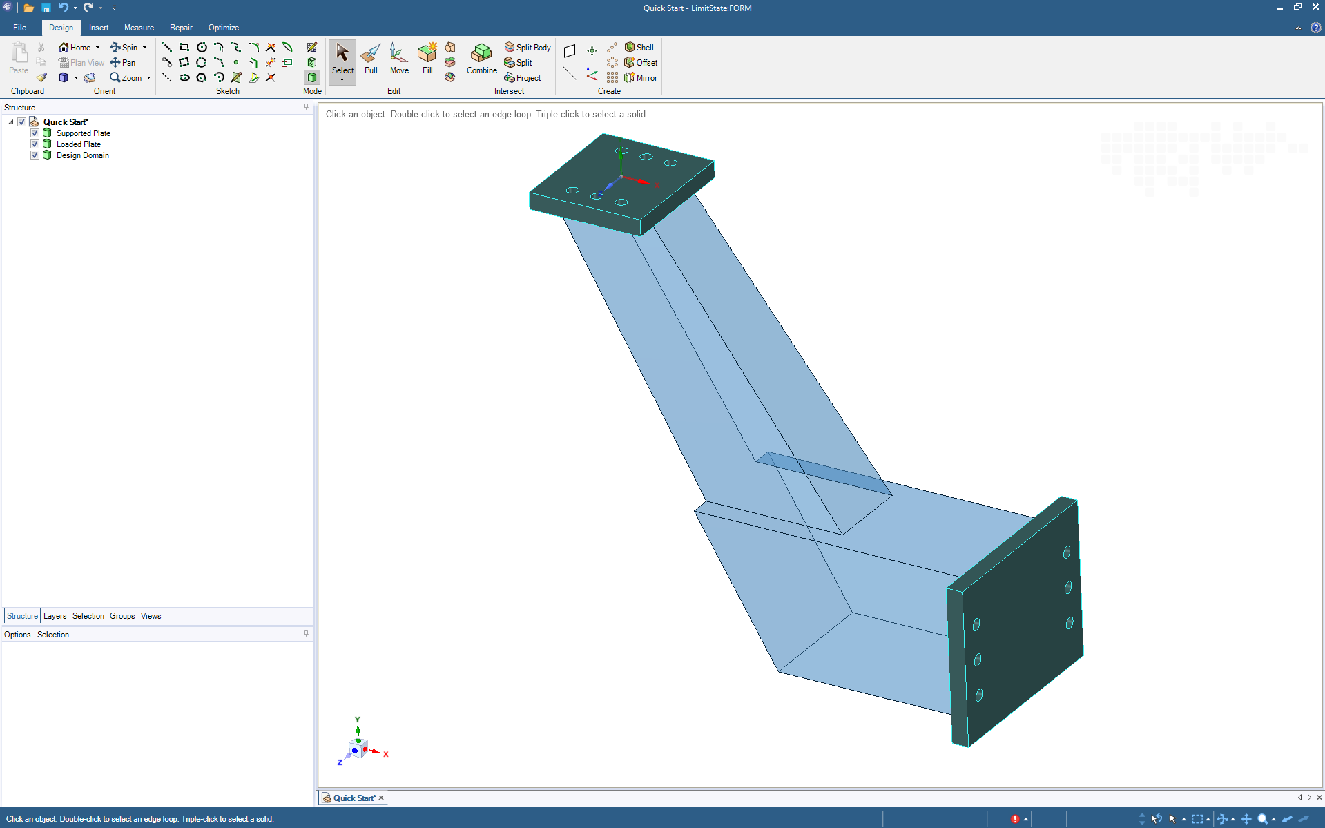
Stage 1 - Define Geometry
Getting started with LimitState:FORM is easy. Just import a CAD file describing the design domain - most major file formats are supported. Or define the design domain directly using the software, which includes powerful direct modelling (CAD) functionality powered by ANSYS SpaceClaim.
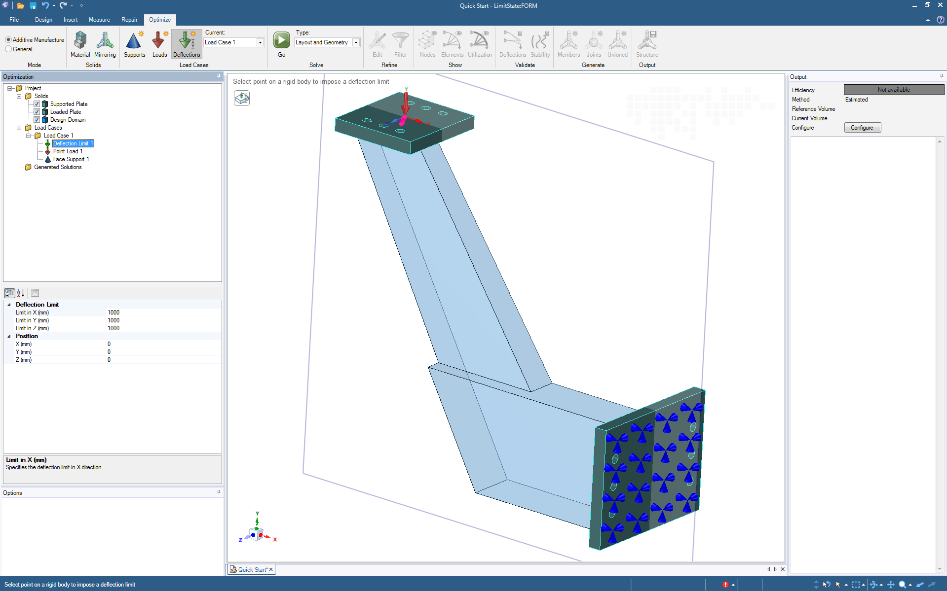
Stage 2 - Specify Inputs
After identifying the design domain, just add materials, loads, supports and deflection limits as required.
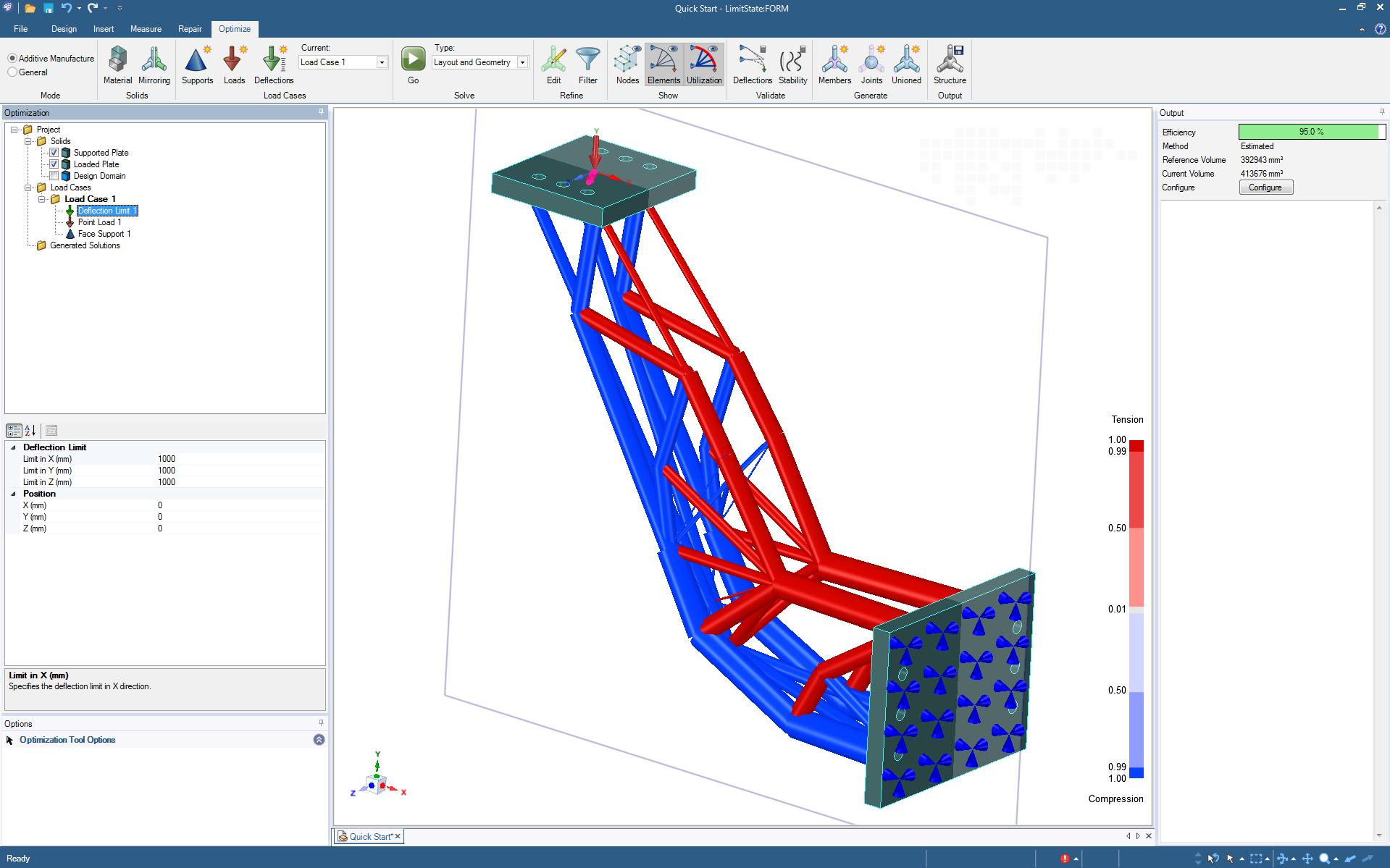
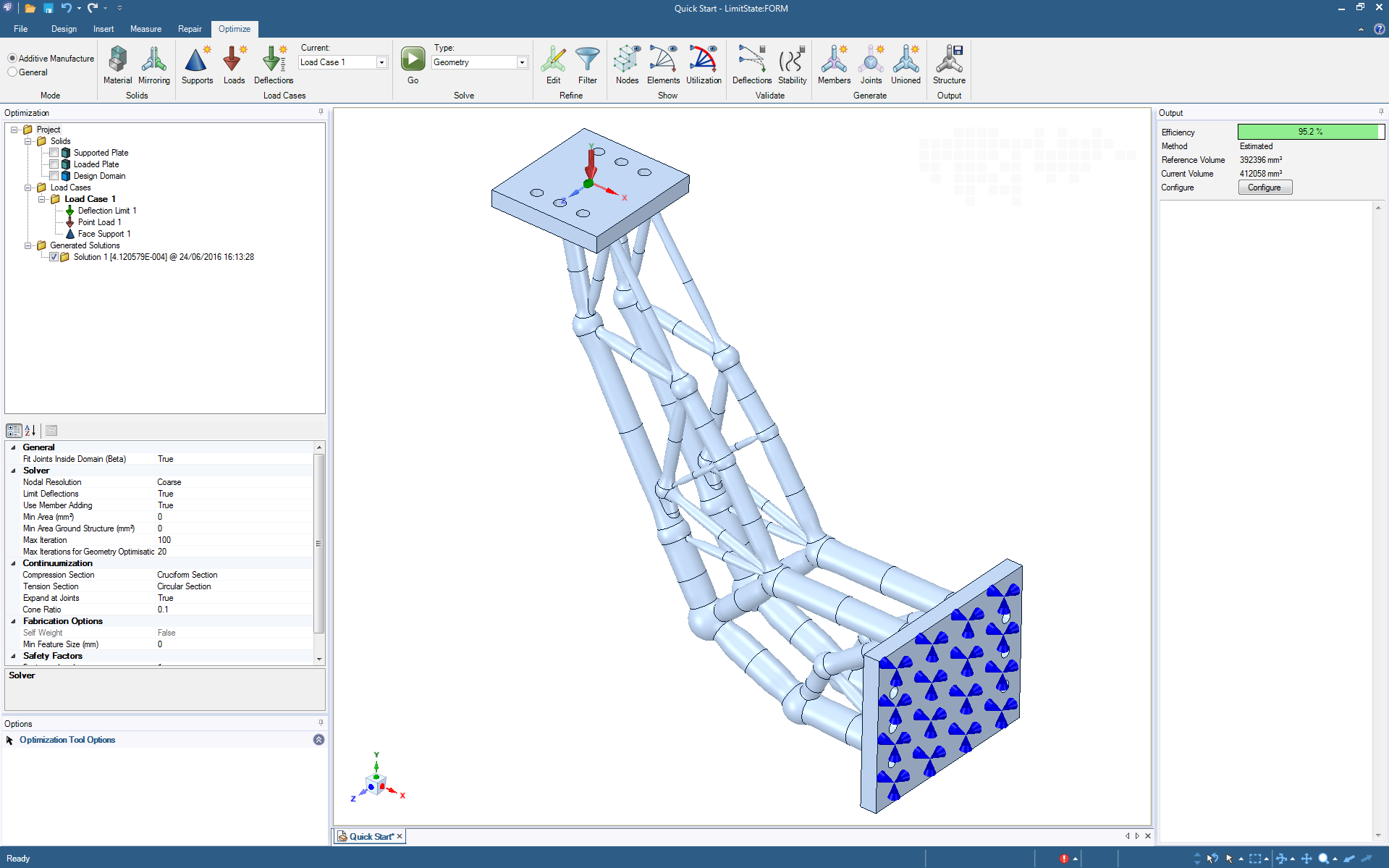
Stage 3 - Optimize
Click ‘solve’ and LimitState:FORM will quickly identify an optimized structural layout, and indicate how efficient it is. There is no need to interpret irregular mesh or voxelized output - the solution is in the form of parametric geometry ready for editing or export.
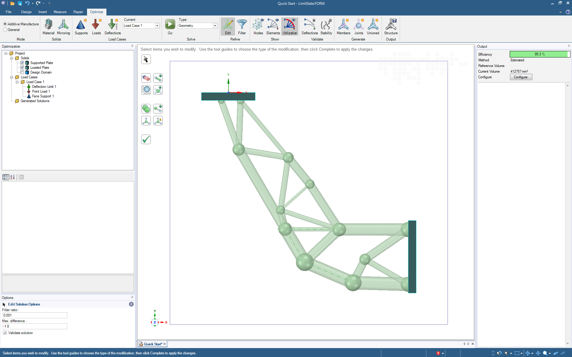
Stage 4 - Refine
Refining the optimized geometry is easy. Merge joints, delete elements, set minimum areas and more. At each stage, the structure is checked for structural integrity and the structural efficiency is reported.
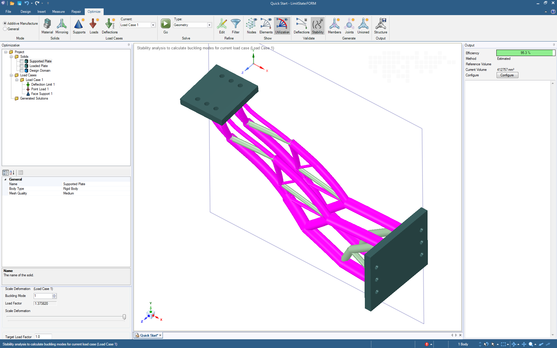
Stage 5 - Validate
Once a candidate geometry has been chosen, the built-in validation tools can be used to check deflections and the potential for elastic instability.
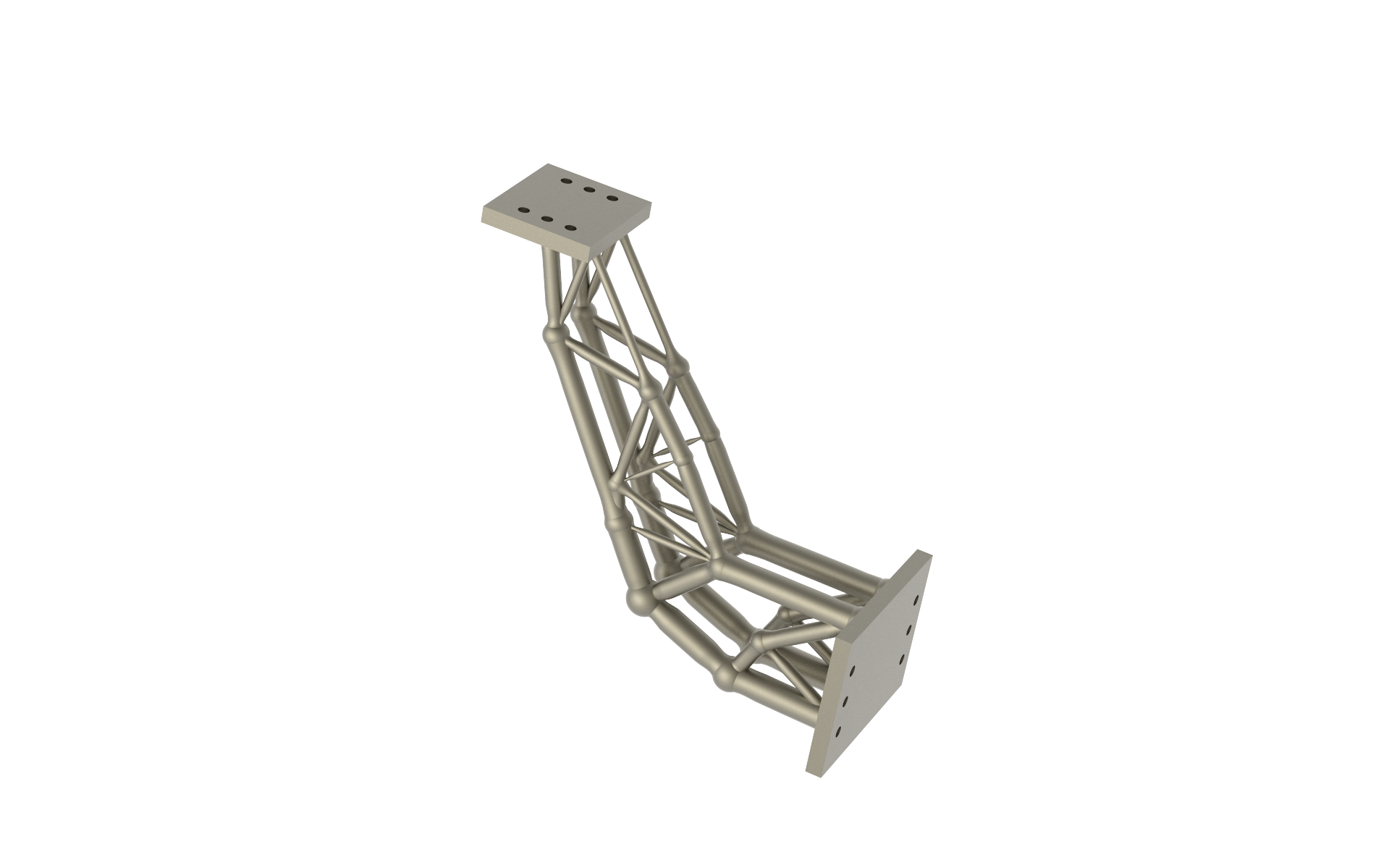
Stage 6 - Create the Final Design and Export
A unioned geometry containing all elements of the model can now be created. Built-in direct modelling CAD tools can be used to add additional features or embellishments, prior to exporting the model for manufacture, or for in-depth FEA verification
Stage 7 - Manufacture
The geometry exported from LimitState:FORM can be read into third-party software, e.g. to prepare the design for additive manufacture.
