1
2
3
4
5
6
7
8

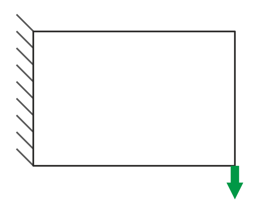
Step 1
A design domain, loading, supports and material properties are defined.
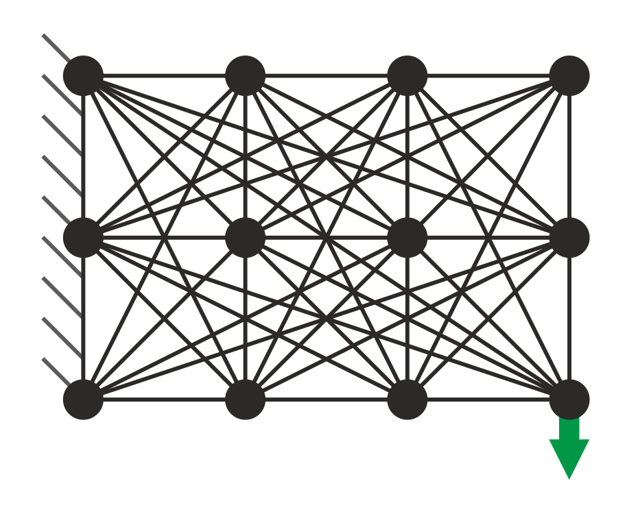
Step 2
The design domain is discretized with nodes (calculation points). Each node is connected to the others using potential members.
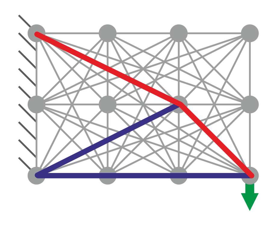
Step 3
A layout optimization stage identifies the optimum (least volume) group of potential members required to resist the applied loading.
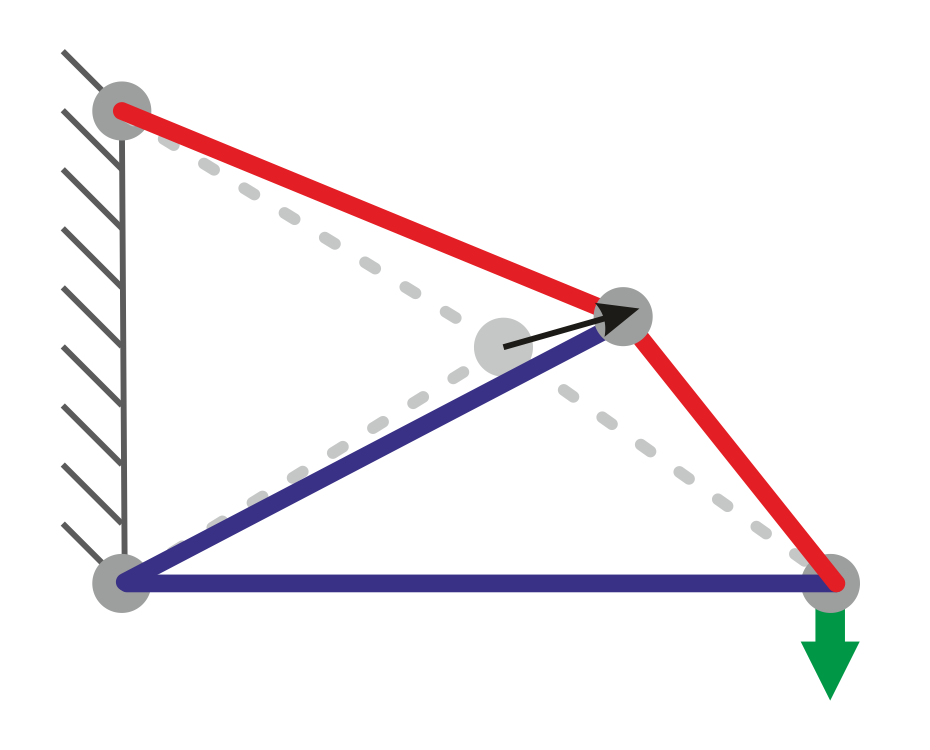
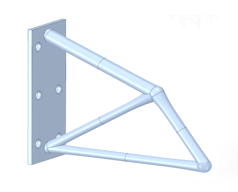
Step 4
A geometry optimization stage adjusts the positions of joints in the optimized structure to further refine the solution and to increase the efficiency.
Step 5
Elastic deflections can be checked (optional).
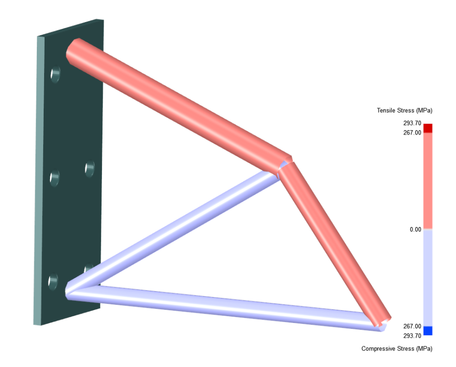
Step 6
Further elastic validation checks can be carried out (e.g. bending stresses shown) and the design can be adjusted accordingly (optional).
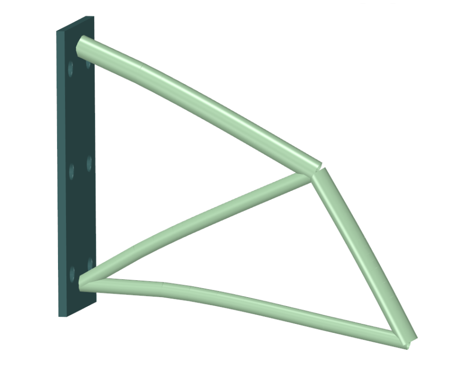
Step 7
A single, unioned, CAD geometry is generated.
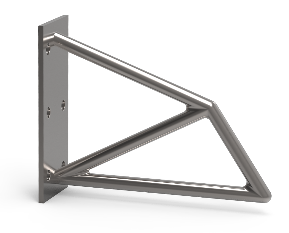
Step 8
The design is exported for further checks (e.g. in FEA software - not shown) or sent for manufacture.
